OrCAD Capture CIS

OrCAD Capture Schematic

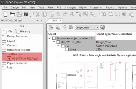
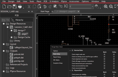
OrCAD Capture schematic entry tool for circuit diagrams is one of the world's most widely used software for entering and documenting electrical circuits. It is outstanding how simple and intuitive the design intentions are captured. OrCAD Capture uses flat or hierarchical circuit diagrams. Via the navigation window the different pages of the circuit diagram can be selected and thematically managed.

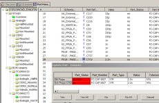
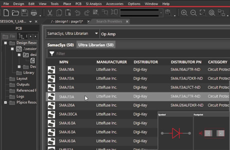
Using the PartBrowser, circuit diagram symbols are selected with the aid of filters from the library and placed in the circuit diagram. The electrical connections (networks) between the associated component pins can be quickly established. In the case of hierarchically structured designs, the same electrical networks are interconnected via cross-porting ports or defined as global networks.

Variants are defined in the schema editor and later output as variants with different parts lists for each variant. In OrCAD Capture can be created with a PCB by means of different mounting devices with a varied range of functions. If programmed components are used in the circuit, pin assignments and signals from FPGAs from different manufacturers can be read. It also supports a design methodology that integrates the vendor tools of the FPGA manufacturers into the place and route of programmable blocks. Changes in the logic can be easily imported into the circuit diagram. OrCAD Capture is also the module for switching inputs from PSpice network lists to simulate analog and mixed-signal circuits.

For designs incorporating programmable devices (such as FPGAs), an Engineering Change Order (ECO) flow is supported, which synchronizes various work steps in the FPGA tool, the circuit diagram, and the PCB editor by forward and backward annotation. Using the CIS option, circuit diagram symbols and data sheets from online databases can be placed directly in the circuit diagram. The CIS option also allows you to transfer component information from a company-owned database.

Product Features

Capture CIS includes all features from OrCAD Capture plus the funktionality of the Component Information System CIS below:

Online Database Link

Online Database Link

OrCAD Capture CIS can communicate directly with an ODBC interface relational databases (e.g., SQL, Access) and database management systems. Thus, the search in the Component Browser extends to metadata such as Price or PDF data sheets. It is connected to the data of the Databases accessed. It can be part numbers, EOL information or Second-source information is managed centrally and via the connection in Capture CIS.

Extended Component Browser

Extended Component Browser

OrCAD Capture CIS has an advanced component browser that allows the user to select components parameterized. The component library can also be synchronized via an ODBC interface with a database (e.g., ERP) in the enterprise. This is useful if e.g. the availability and price of components not be maintained by the development, but from another department within the company. Thus, information about discontinued or not released components can already be considered in the design of the circuit.

Variants
Variants

Variants

Based on a printed circuit board, different devices can be used with different types of components generate different levels of expansion or different customers. Variants can be found in it exist that a component is equipped with a different value. Same components with different Values are colored green in the example on the left. With the CIS option you can omit or additional placement of components the parts list vary. These components are marked red in the left example. This allows you to access bills of material based on a circuit diagram and generate variants of the circuit diagram. Different assembly drawings can then output in the PCB Editor.

OrCAD Capture testbench for PSpice
Capture testbench for PSpice

OrCAD Capture Testbench for PSpice

OrCAD Capture is a schematic entry tool to capture the design intent of an electronic circuit. Schematics capture the netlist and drive later in the design process the layout of a PCB. During development OrCAD Capture can be used to run circuit simulations with PSpice. Select an area or the circuit and create a live copy as a testbench. Now you can apply voltages and probes for simulation on the virtual copy of the schematic. Optimization and documentation of wave forms stays in sync with the master schematic for the layout.

Video Tutorials

See these video tutorials, which explain several technical features in detail:

OrCAD Capture CIS Training Classes

Public training classes are offered on a regular basis. In the table below you will see the time table, when these classes are offered. In addition you can ask for your own training on your site, which makes business sense, when you have five or more person attend the same class form one company. Customization of trainings is possible too.

YouTube Videos

3:02

Why OrCAD

OrCAD Capture is one of the most widely used schematic design solutions for the creation and documentation of electrical circuits. Fast, easy, and intuitive circuit capture, along with highly integrated flows supporting the engineering process, make OrCAD Capture one of the most popular design environments for today’s product creation.

Real-Time Feedback and ECO
1:15

Customize Workspace

Simulating your designs allows you to be aware of the limitations of your components. It’s important to analyze your circuit before moving to layout. Analysis helps identify possible field failures allowing you to reduce development time and cost.

Real-Time Feedback and ECO
1:15

Real-Time Feedback and ECO

Real-time feedback and design synchronization helps keep the data between your CAD tools in check, so you don’t have to manually identify and resolve the errors or differences. As you work on your schematic, enable the online DRC check for any rule to be automatically notified of any issues that occur as you design. Clicking on any of the warnings or errors from the list, immediately takes you to the issue on the canvas. Once you’ve resolved the errors, you can easily compare the data in your schematic versus the data in your PCB editor and see a preview of what has been modified between the designs.

Unified Part Search
1:15

Unified Part Search

Easily access an up-to-date database with datasheets, symbols, footprints, 3D models and part descriptions from the provided vendors to place parts within your schematic.